Design Method and How it Affects the Cost, Weight and Lifetime of the Project
Design Method and How it Affects the Cost, Weight, and Lifetime of the Project In…

Structural bolts play a crucial role in ensuring the stability and safety of any construction project. These specialized bolts are designed to withstand heavy loads and provide a secure connection between structural components. Whether you are building a bridge, a skyscraper, or even a small residential structure, choosing the right structural bolt is of utmost importance. In this comprehensive guide, I will take you through everything you need to know about selecting and installing the perfect structural bolt for your project.
Structural bolts come in various types, each with its unique features and applications. The most common types include:
A490 bolts are similar to A325 bolts but are made from alloy steel. They are used in heavy construction projects that require high tensile strength.
A490 bolts are similar to A325 bolts but are made from alloy steel. They are used in heavy construction projects that require high tensile strength.
These bolts feature a spline end and a unique installation method that ensures proper tensioning. They are commonly used in structural steel connections.
A307 bolts are low-strength bolts made from low carbon steel. They are generally used for erection purposes. A307 are generally called as erection bolts, unfinished bolts, machine bolts or soft bolts.
| A325 | A490 | ||
| Chemical Composition | High strength carbon steel bolts | Quenched and tempered alloy steel bolts | |
| Strength and Cost | Strength and cost both are less compared toA490 bolts | Strength and cost are high compared to A325 bolts | |
| Washers | Standard, Oversized and Short Slotted Holes | Standard ASTM F436 washer for all the bolt diameters | Standard ASTM F436 washer for up to 1″ diameter bolt |
| Long Slotted Holes | 5/16″ thick plate washer or continuous bar | ASTM F436 with 5/16″ thick washer.3/8″ thick plate washer or continuous bar bolt diameter greater than 1″ | |
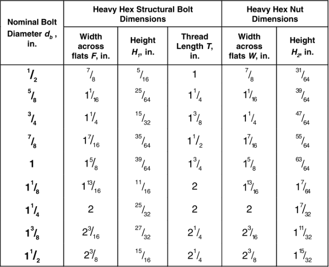
Both A325 and A490 bolts are available in ½” to 1 ½” diameter and length generally up to 8”

a This requirement shall not apply to heads of round-head tension-control bolt assemblies that meet the requirements in Section 2.7 and provide a bearing circle diameter that meets the requirements of ASTM F1852.
b Multiple washers with a combined thickness of 5/16 in. or larger do not satisfy this requirement.
c The plate washer or bar shall be of structural-grade steel material but need not be hardened.
d Alternatively, a 3/8-in thick plate washer and an ordinary thickness F436 washer may be used. The plate washer need not be hardened.
| ASTMDesignation | NominalBoltDiameter,d b , in. | Hole Type in Outer Ply | ||
| Oversized | Short-Slotted | Long-Slotted | ||
| A325 orF1852 | ½-1½ | ASTM F436a | 5/16-in.-thick platewasher orcontinuous barb, c | |
| A490 | <= 1 | |||
| > 1 | ASTM F436 with 5/16 in.Thickness b, d | ASTM F436 washer with either a 3/8-in.-thick structural grade plate washer or continuous barb | ||
RCSC – Table 6.1
RCSC – Table C-2.1
Acceptable bolt stick out is established by the bolt and nut combination. Below is a chart that details general guidelines for acceptable bolt stick out. Note that any protrusion beyond these guidelines may still be suitable.


In a bearing joint the connected elements are assumed to slip into bearing against the body of the bolt. If the joint is designed as a bearing joint the load is transferred through bearing whether the bolt is installed snug-tight or pretension.
All connected plies that are within the grip of the bolt and any materials that are used under the head or nut shall be steel (uncoated, coated or galvanized). Compressible materials shall not be placed within the grip of the bolt. The slope of the surfaces of parts in contact with the bolt head and nut shall be equal to or less than 1:20 with respect to a plane that is normal to the bolt axis.
Faying surfaces and surfaces adjacent to the bolt head and nut shall be free of dirt and other foreign material.

The faying surfaces in slip-critical joints require special preparation. The faying surfaces of slip-critical joints including those of filler plates and finger shims, shall meet the
following requirements:
Uncoated faying surfaces shall be free of scale, except tight mill scale, and free of coatings, including inadvertent overspray,in areas closer than one bolt diameter but not less than 1 in. from the edge of any hole and in all areas within the bolt pattern.
The faying surfaces of snug-tightened joints and pretensioned joints are permitted to be uncoated, coated with coatings of any formulation or galvanized.
Coated faying surfaces shall first be blast cleaned and subsequently coated with a coating that is qualified in accordance with the requirements in Appendix A as a Class A or Class B coating.
Galvanized faying surfaces shall first be hot-dip galvanized in accordance with the requirements of ASTM A123 and subsequently roughened by means of hand wire brushing. Power wire brushing is not permitted. When prepared by roughening, the galvanized faying surface is designated as Class C for design.

Faying surfaces of slip-critical connections painted with unqualified paints
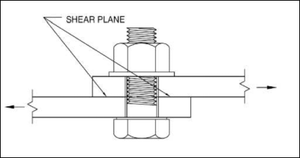
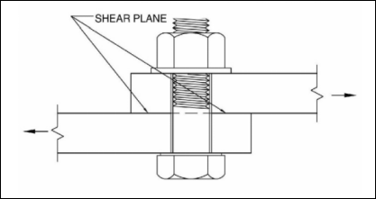
The shear plane is the plane between two or more pieces under load where the pieces tend to move parallel from each other, but in opposite directions.
In N-type the threads are included in the shear plane.
In X-type the threads are excluded in the shear plane.
The capacity of a bolt is greater with the threads excluded from the shear plane
The nominal dimensions of standard, oversized, short-slotted and long-slotted holes for high-strength bolts shall be equal to or less than those shown in the belowTable-3.1. Thermally cut bolt holes shall be permitted if approved by the Engineer of Record. For statically loaded joints, thermally cut surfaces need not be ground. For cyclically loaded joints, thermally cut surfaces shall be ground smooth.

RCSC-Table 3.1. Nominal Bolt Hole Dimensions
In the absence of approval by the Engineer of Record for the use of other hole types, standard holes shall be used in all plies of bolted joints.
When approved by the Engineer of Record, oversized holes are permitted in any or all plies of slip-critical joints.
When approved by the Engineer of Record, short-slotted holes are permitted in any or all plies of snug-tightened joints, and pre-tensioned joints, provided the applied load is approximately perpendicular (between 80 and 100 degrees) to the axis of the slot. When approved by the Engineer of Record, short-slotted holes are permitted in any or all plies of slip-critical joints as defined in Section 4.3 without regard for the direction of the applied load.
When approved by the Engineer of Record, long-slotted holes are permitted in only one ply at any individual faying surface of snug-tightened joints, and pre-tensioned joints as defined in Section 4.2, provided the applied load is approximately perpendicular (between 80 and 100 degrees) to the axis of the slot. When approved by the Engineer of Record, long-slotted holes are permitted in one ply only at any individual faying surface of slip-critical joints as defined in Section 4.3 without regard for the direction of the applied load. Fully inserted finger shims between the faying surfaces of load-transmitting elements of bolted joints are not considered a long-slotted element of a joint; nor are they considered to be a ply at any individual faying surface.
Distance between the centers of standard, over sized or slotted holes shall not be less than 2 2/3 times the nominal diameter, d. of the fastener.A distance of 3d is preferred.
The distance from the center of the standard hole to an edge of a connected part in any direction shall not be less than the value from the AISC table J3.4

The distance from the center of an over-size or slotted hole to the edge of a connected part shall not be less than the required for a standard hole to the edge of a connected part plus the applicable increment C2 from the AISC table-J3.5

The snug-tightened condition is typically achieved with a few impacts of an impact wrench application of an electric torque wrench until the wrench begins to slow or the full effort of a worker on an ordinary spud wrench. More than one cycle through the bolt pattern may be required to achieve the snug-tightened joint.
In this type the tightening is achieved by extra tightening of the head/nut as per RCSC table-8.2 from the snug tight condition, using an impact wrench.

Achieved by using calibrated wrench by applying the minimum torque as per the RCSC table-7-1 from snug tight condition.
ASTM F1852 & F2280 twist-off type tension control bolt assemblies have a splined end that exceeds the threaded portion of the bolt. During installation, this splined end is gripped by a specifically designed wrench chuck and provides a means for turning the nut relative to the bolt. The splined end will shear off after reaching the minimum pretension
DTI are hardened, washer shaped devices incorporating small arch like protrusion on the bearing surface that are designed to deformed in a controlled manner when subjected to control load.
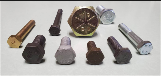
The ASTM requires structural bolts to be distinctively marked. These bolt head markings include the manufacturer’s mark, the grade of bolt (ex. A325, A490), and markings to classify the type of bolt (Type 1 or Type 3).
In addition to the mandatory markings, certain manufacturers may include additional markings to distinguish them from others.

RCSC – Figure C-2.1
The structural integrity of any building or infrastructure relies heavily on the quality and suitability of the bolts used. A weak or incorrectly chosen bolt can compromise the entire structure, leading to potential disasters. It is essential to invest time and effort in selecting the right structural bolt that meets the specific requirements of your project. By doing so, you ensure the safety of those who will use and rely on the structure in the future.
Choosing the right structural bolt involves considering several important factors. These factors include:
The bolt must have the required load capacity to withstand the forces acting upon it. This includes considering the weight of the structure, wind loads, seismic loads, and any other relevant factors.
Consider the environmental conditions and the type of structure being built to select a bolt material that provides the necessary strength and corrosion resistance.
Choose the appropriate bolt size based on the thickness of the materials being connected and the required grip length.
Depending on the environment in which the structure will be located, it is crucial to choose a bolt with appropriate corrosion resistance. This ensures that the bolt will not weaken or fail over time due to corrosion.
The bolt should be compatible with the materials being joined. For example, if the structure is made of stainless steel, it is important to use a bolt made of a similar material to prevent galvanic corrosion.
By carefully considering these factors, you can choose a structural bolt that meets the specific needs of your project and ensures its safety and strength.
Proper installation of structural bolts is critical to maintaining the integrity of the structure. Follow these guidelines to ensure a secure and reliable installation
Make sure the holes are clean, free from debris, and properly aligned. Use a template or guide to ensure accurate hole drilling
Use a calibrated torque wrench to tighten the bolt to the recommended torque value. Over-tightening can lead to bolt failure, while under-tightening can result in a loose connection.
After installation, visually inspect the bolts to ensure they are properly seated and tightened. Check for any signs of damage or misalignment.
Keep a record of the installation process, including torque values, for future reference and maintenance.
Regular maintenance and inspection of structural bolts are crucial for ensuring their long-term performance and safety. Here are some key practices to follow:
Regularly inspect the bolts for signs of corrosion, deformation, or damage. Address any issues promptly to prevent further deterioration.
Periodically check the bolt tightness using a calibrated torque wrench. Retorque any bolts that have become loose due to settlement or vibration.
Apply appropriate corrosion protection measures, such as coatings or galvanizing, to prevent rust and deterioration.
Maintain a comprehensive record of inspections, maintenance activities, and any repairs or replacements performed on the bolts.
Choosing and installing the perfect structural bolt is a critical aspect of any construction project. The safety and longevity of the structure depend on the quality and suitability of the bolts used. By understanding the different types of structural bolts, considering the necessary factors, and following proper installation and maintenance guidelines, you can ensure a secure and reliable connection. Remember to consult with experts, refer to industry guidelines, and choose a reputable supplier to obtain high-quality structural bolts for your project. Invest in the right bolt, and you’ll have peace of mind knowing that your construction is built to last.
Apply appropriate corrosion protection measures, such as coatings or galvanizing, to prevent rust and deterioration.
Design Method and How it Affects the Cost, Weight, and Lifetime of the Project In…
The Ultimate Guide to Structural Steel Stairs What are Stairs? Stairs allow individuals to move…
The Ultimate Guide to BRB The brace that attempts to inhibit buckling under compression is called…
Structural Bolts Structural bolts play a crucial role in ensuring the stability and safety of…

The Ultimate Guide to AESS This guide dives into the nitty-gritty of AESS steel, covering…

Steel detailing is a meticulous task that demands high precision. However, even experienced detailers can…