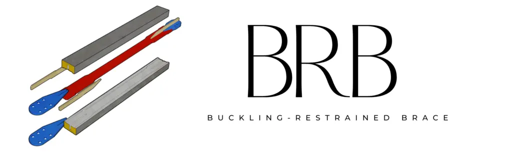
The brace that attempts to inhibit buckling under compression is called BRB (Buckling Restrained Brace). A BRB allows the building to withstand cyclic lateral loading, typically earthquake-induced. A BRB can yield both in tension and compression without buckling.
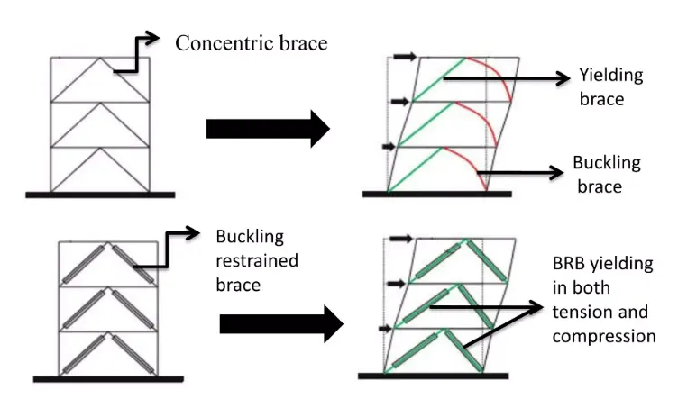
Why to use BRB?
A Normal Brace under loading has several disadvantages
- 1.Connection failure
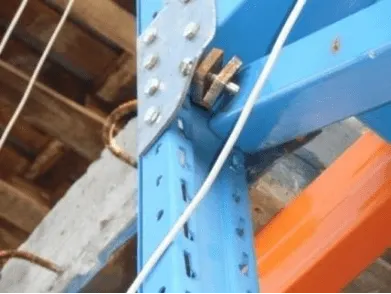
- Member fracture
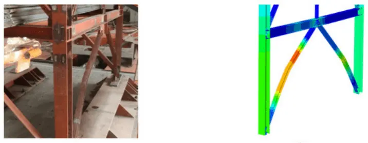
- Loss of strength and stiffness
- Degradation of brace capacity and stiffness
- Undesirable system response
A BRB eliminates all these disadvantages.
History of BRB
The concept of BRBs was developed in Japan by Nippon Steel at the end of the 1980s and was known by its trademark name of Unbonded Brace.
It was first installed in the United States in 1999, in the Plant & Environmental Sciences Building in U.C. Davis. In 2002, both CoreBrace LLC and Star Seismic LLC were incorporated, and began competition with Nippon in the BRB design market.
BRB usage is currently accepted, with its design regulated in current standards, throughout the world.
Components of BRB
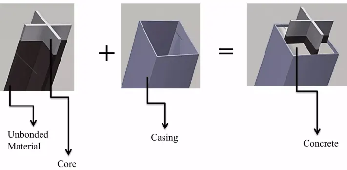
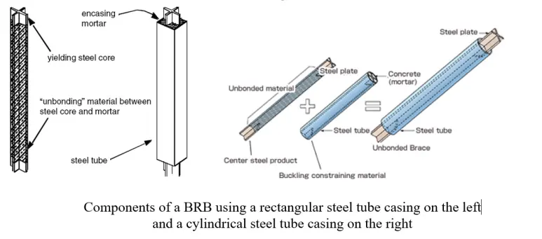
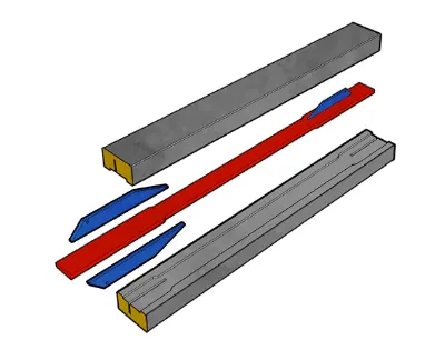
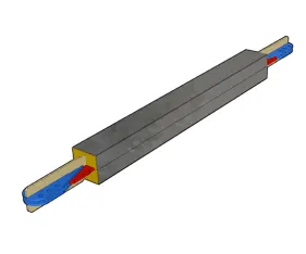
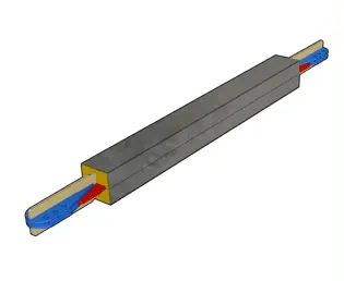
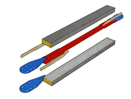
Three major components of a BRB are
- Steel core
- Bond-Preventing Layer
- Casing
1. Steel core
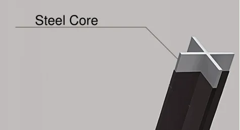
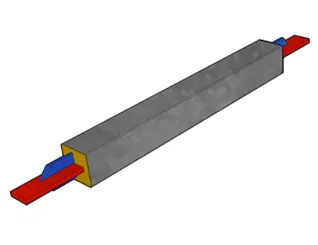
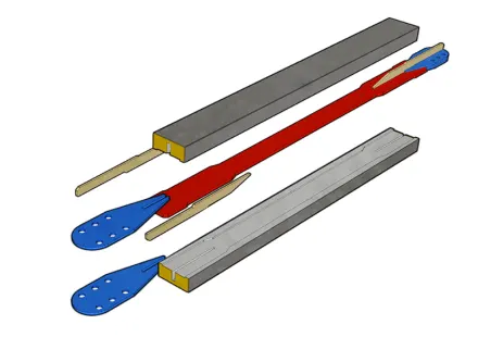
The steel core is designed to resist the full axial force developed in the bracing. Its cross-sectional area can be significantly lower than that of regular braces, since its performance is not limited by buckling. The core consists of a middle length that is designed to yield in elastically in the event of a design-level earthquake and rigid, non-yielding lengths on both ends. Increased cross-sectional area of the non-yielding section ensures that it remains elastic, and thus plasticity is concentrated in the middle part of the steel core. Such configuration provides high confidence in prediction of the element behavior and failure.
2. Bond-Preventing Layer
The bond-preventing layer decouples the casing from the core. This allows the steel core to resist the full axial force developed in the bracing, as designed.

3. Casing
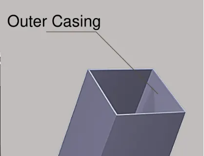
The casing – through its flexural rigidity – provides the lateral support against flexural buckling of the core. It is typically made of concrete-filled steel tubes. The design criterion for the casing is to provide adequate lateral restraint (i.e. rigidity) against the steel core buckling.
Characteristics of BRB
- Because BRBs achieve a high level of ductility and stable, repeatable hysteresis loops, BRBs can absorb significant amount of energy during cyclic loading, such as an earthquake event.
- Preventing buckling leads to similar strength and ductile behavior in compression and tension, illustrating the envelope of the hysteresis curves, also referred as a backbone curve. This curve is considered as an important basis of practical design. The beneficial cyclic behavior of the steel material can therefore be extrapolated to an element level and thus to the overall structural level and extremely dissipative structure can be designed using BRBs.
- Experimental results prove the ductile, stable and repeatable hysteretic behavior of structures built with BRBs.Depending on the configuration of braces, the building codes in the United States allow the use of a response modification factor up to 8, that is comparable to special moment resisting frames (SMRFs); a higher response modification is associated with greater ductility, and thus enhanced post-yielding performance. Thus, the seismic load applied to the structure is efficiently reduced, which results in smaller cross sections for the beams and columns of the braced frames, smaller demands on the connections and, most importantly, the loads on the foundation are drastically decreased.
BRB Connection
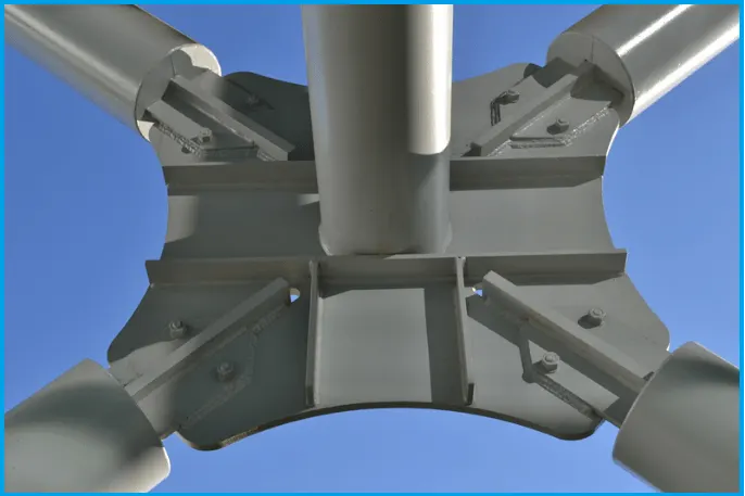
The purpose of buckling-restrained braces is to dissipate lateral forces from columns and beams. Therefore, the connection of the braces to beams and columns can greatly affect the performance of the brace in the case of a seismic event. Typically, the brace is attached to a gusset plate, which in turn is welded to the beam and/or column that the brace will be attached to.
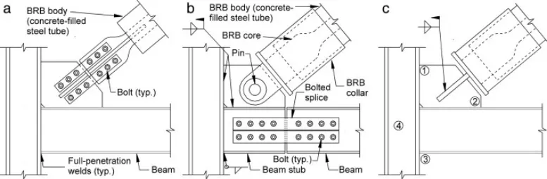
Types of BRB Usually three types of connections are used for BRBs
- Welded BRB Connection
The brace is fully welded to the gusset plate in the field. Although this option requires additional man-hours on-site, it can increase the performance of the brace itself by improving the force transfer mechanism, and potentially lead to smaller braces.
Welded BRB Connections on Site

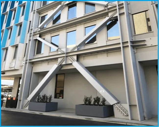
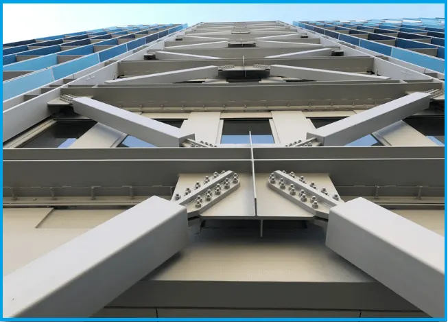
- Bolted BRB Connection
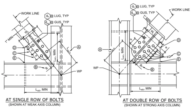
The brace is bolted to the gusset plate in the field.
Bolted BRB Connections on Site
Picture-2.3
3. Pinned BRB Connection
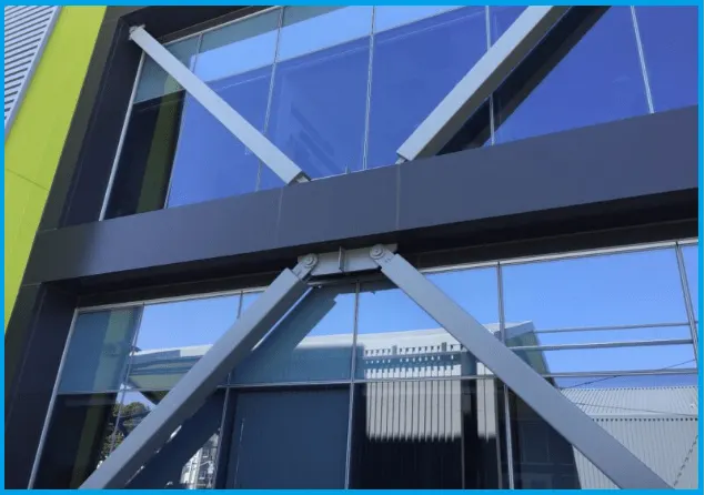
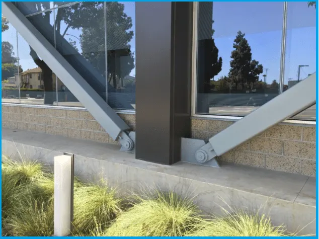
The brace and gusset plate are both designed to accept a pin, which connects them to each other and allows for free rotation. This can be beneficial to the design engineer if he or she needs to specify a pinned-type connection.
In addition to the connection type, the details of the connection can also affect the transfer of forces into the brace, and thus its ultimate performance. Typically, the brace design firm will specify the proper connection details along with the brace dimensions.
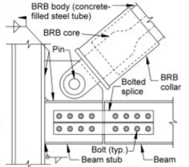
Pinned BRB Connections on Site
Advantages of BRB
Comparative studies, as well as completed construction projects, confirm the advantages of buckling-restrained braced frame (BRBF) systems. BRBF systems can be superior to other common dissipative structures with global respect to cost efficiency for the following reasons:
Buckling-restrained braces have energy dissipative behavior that is much improved from that of Special Concentrically Braced Frames (SCBFs). Also, because their behavior factor is higher than that of most other seismic systems, and the buildings are typically designed with an increased fundamental period, the seismic loads are typically lower. This in turn can lead to a reduction in member (column and beam) sizes, smaller and simpler connections, and smaller foundation demands. Also, BRBs are usually faster to erect than SCBFs, resulting in cost savings to the contractor. Additionally, BRBs can be used in seismic retrofitting. Finally, in the event of an earthquake, since the damage is concentrated over a relatively small area (the brace’s yielding core), post-earthquake investigation and replacement is relatively easy.
An independent study concluded that the use of BRBF systems, in lieu of other earthquake systems, produced a cost per square foot savings of up to $5 per square foot.
Disadvantages of BRB
Buckling restrained braces rely on the ductility of the steel core to dissipate seismic energy. As the steel core yields, the material work-hardens and becomes stiffer. This work hardening can represent increases in the expected force of up to 2x the initial yield force. This increased stiffness decreases the building’s period (negating some of the initial increases) and increases the expected spectral acceleration response requiring stronger foundations and connection strengths.
Buckling restrained braces rely on ductility and generally must be replaced after usage during a major earthquake.
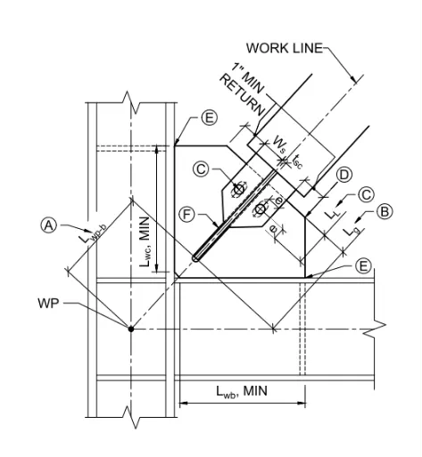
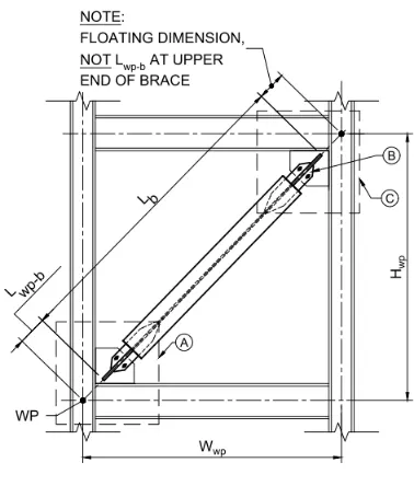
BRB Symbols Wwp = Width of frame bay workpoint (WP) to WP
Hwp = Height of frame bay WP to WP
Lb = Length of CB end to end of core
Lwp-b = Length from WP to bottom end only of CB
e = Typical erection bolt edge distance
Dwg = Size of weld for core to gusset
Dwsg = Size of weld for core stiffeners to gusset
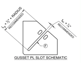
Lg = Length of core lap on gusset
LL = Length of stiffener lap on gusset
Le = Length of core beyond core stiffener
ts = Thickness of core stiffener
Ws = Width of core stiffener
tg = Thickness of gusset
Fy,g&r = Gusset A572 grade
tsc = Thickness of core
db = Diameter of erection bolts
L’ = Length of bolt needed with F436 washer only
La = Suggested Length of bolt to order, detailer to verify
Wb = Minimum size of beam weld
Lwb = Minimum length of beam weld
Wc = Minimum size of column weld
Lwc = Minimum length of column weld
Lgb = Approximate maximum width of gusset rounded up to nearest inch
(At V or Chev, equal to 1/2 gusset width)
Lgc = Approximate maximum height of gusset rounded up to nearest inch
Gusset Overall Layout Procedure
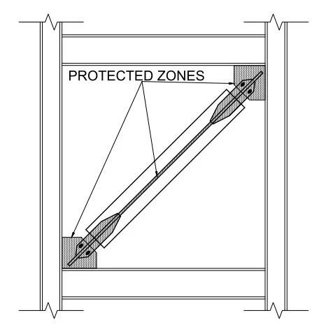
BRB Protected Zones
DisclaimerEducational use only. Not engineering, legal or code-compliance advice.
The content on StructuralWorld, including articles, diagrams, calculators and other tools, is provided for general educational and informational purposes only. It is not engineering, architectural, legal or code-compliance advice, and it does not create a professional relationship between you and StructuralWorld or its authors.
Codes, standards and regulations (for example OSHA, IBC, ADA and AISC) are revised regularly and are adopted and amended differently by each jurisdiction. Figures shown here may be simplified, may refer to a specific edition, and may be out of date or contain errors. Calculators and interactive diagrams are illustrative only and are not a substitute for design calculations, shop drawings or engineering review.
Before relying on any information for design, fabrication, erection, inspection or safety decisions, verify it against the current governing code and the project documents, and consult a qualified, licensed professional (such as a structural engineer) and the authority having jurisdiction.
To the fullest extent permitted by law, StructuralWorld and its authors make no warranties, express or implied, about the accuracy, completeness or fitness for a particular purpose of this content, and accept no liability for any loss, damage or injury arising from its use or from reliance on it. Links to third-party standards and websites are provided for convenience; that material belongs to its owners. If you find an error, please let us know.